
In addition to the motherboard connectors, everything Power supplies are also equipped with various additional connectors, most of which are designed to power disk drives and other peripherals, such as a powerful video card. Most peripheral connectors, in turn, comply with industry standards for one form factor or another. In this part of our material, we will look at what additional connectors you can find in your PC.
Peripheral Power Connector
Perhaps the most common type of connector that can be found on all PSUs is the power connector. peripherals, which is also often referred to as a disk drive power connector. What we mean by this type of connector first appeared in AMP power supplies in the PSU series and was called the MATE-N-LOK connector, but since it began to be manufactured and sold by Molex, it has also been called the "Molex connector", which is not entirely correct.
To determine the location of the contacts, carefully look at the connector. As a rule, on the right side of the plug there is a plastic ledge and a key, which is necessary for the correct fixation of the connector in the socket. The following diagram shows a standard keyed plug. It is this connector that is used to power disk drives (and not only):
Peripheral Power Connector
This connector has been used on all PCs, from the original IBM PC to modern systems. It is most commonly known as a disk drive connector, but is also used on some systems for additional food motherboard, video card, cooling fans and any other PC components that can use +5 V or +12 V.
This is a 4-pin connector that has four round-shaped contacts spaced 5mm apart and rated for up to 11A each. Since the connector includes one +12 V and one +5 V pin (the other two are ground), the maximum current through the connector reaches 187 watts. The male connector is about 2 cm wide and can be connected to most disk drives and some other PC components. The following table shows the pin assignment on this connector:
| Contacts on the power connector for peripheral devices | |||||
| Contact | Signal | Color | Contact | Signal | Color |
| 1 | +12V | Yellow | 3 | Gnd | The black |
| 2 | Gnd | The black | 4 | +5V | Red |
Floppy drive power connector
In the mid-1980s, 3.5-inch magnetic disk drives first appeared, and then it became clear that they needed a more compact power connector. The answer was what is today known as the floppy drive power connector, which was developed by AMP as part of the EI (Economy Interconnection) series. These connectors are used to power small disk drives and devices, and have the same +12V, +5V and ground pins as the large peripheral connector. The distance between the contacts in this type of plug is 2.5 mm, and the plug itself is about half the size of the large connector. All pins are rated at 2A each, so the maximum current through this connector is only 34W.
The following table shows the pin configuration on the floppy drive power connector:
| Contacts on the floppy drive power connector | |||||
| Contact | Signal | Color | Contact | Signal | Color |
| 1 | +5V | Red | 3 | Gnd | The black |
| 2 | Gnd | The black | 4 | +12V | Yellow |
The peripheral power connector and its younger brother have a universal pin layout, as can be seen in the following diagram:
Peripheral power connector and floppy drive connector
The pin layout on the floppy connector is a mirror image of the larger peripheral connector. When using an adapter from one type of connector to another, be careful not to forget that in this case the red and yellow wires are reversed.
First Power supplies were equipped with only two connectors for peripherals, while modern PSUs have four or more large connectors and one or two connectors for floppy drives. Depending on the power and purpose, some PSUs have eight or even more connectors for peripheral devices.
If you use a lot of hard drives or other devices that need additional power, you can use a Y-splitter, as well as a large-to-small connector adapter. The splitter allows you to turn one peripheral power connector to connect two drives to it at once, and with an adapter you can use a large connector to power a floppy drive. If you are using multiple adapters, make sure the total power power supply is sufficient. Connectors connected to the splitter should not exceed the capacity of one connector in terms of total load.
Serial ATA power connector
The vast majority of modern hard drives and all SSDs are equipped with a SATA power connector. So, if a few years ago SATA connectors on PSUs were some kind of nice option, then they are mandatory on new power supplies. The SATA (Serial ATA) power connector is a special 15-pin connector that uses only five wires, which means that three pins per connector are connected to one wire. The total power supply through such a connector is exactly the same as that of a conventional peripheral connector, but the SATA cable is noticeably thinner.

SATA power connector
In the SATA power connector, each wire is connected to three pins, and the wire numbering does not match the pin numbering. If your power supply does not have SATA power connectors, you can use an adapter from a regular peripheral connector. However, these adapters do not supply the +3.3V line. Fortunately, this is not a problem for most SATA devices as they do not use the +3.3V line and only use the +12V and +5V voltages.

Peripheral to SATA adapter
Additional power connector for PCI-E video cards
The ATX12V 2.x specification uses a new 24-pin motherboard power connector that provides more power to power various on-board controllers and PCI-E cards. The specification is designed for an additional power of 75 W directly for the PCI-E x16 slot, and this power, in principle, is enough for many video cards with average performance. But high performance graphics cards tend to need higher levels of power. For this reason, the PCI-SIG (Special Interest Group) development group has introduced two standards for providing additional power to PCI-E video cards, which involve the use of the following connectors:
- PCI Express x16 Graphics 150 W-ATX - specification published in October 2004. An additional 6-pin (2x3) connector is used, which provides an additional 75W of power. The total power of the PCI-E x16 slot reaches 150W.
- PCI Express 225 W/300 W High Power Card Electromechanical - Specification published March 2008. Assumes the use of an 8-pin (2x4) auxiliary power connector, providing an additional 150W of power. The total power is 225 W (75+150) or 300 W (75+150+75).
For video cards that require even more power, you can connect several connectors at once:
| PCI-E Auxiliary Power Connector Configurations | |
| Max Power | Add-on configuration food |
| 75 W | Not used |
| 150 W | 1 x 6-pin |
| 225 W | 2 x 6-pin or 1 x 8-pin |
| 300 W | 1 x 8-pin + 1 x 6-pin |
| 375 W | 2 x 8-pin |
| 450 W | 2 x 8-pin + 1 x 6-pin |
PCI Express cards are provided using 6-pin (2x3) or 8-pin (2x4) Molex Mini-Fit connectors, equipped with a female plug that connects directly to the video card. For reference, these connectors are similar to Molex 39-01-2060 (6-pin) and 39-01-2080 (8-pin), but both use different keys to prevent them from being mistakenly plugged into the +12V connector on the motherboard. board. The following diagram shows the layout of the connectors, including the plug side. Notice the "sense" signal on pin 5 - it lets the graphics card know if the connector is connected. Without proper power levels, the card may shut down or operate in reduced functionality mode. Also note that pin 2 is labeled N/C (No Connection) in the table according to the standard specification, but most power supplies seem to accept +12V as well.

6-pin PCI-E 6 pin (2x3) auxiliary power connector, rated for 75 W
| Connector 6 pin (2x3) additional 75-W connector for powering PCI-E video card | |||||
| Color | Signal | Contact | Contact | Signal | Color |
| The black | GND | 4 | 1 | +12V | Yellow |
| The black | sense | 5 | 2 | N/C | - |
| The black | GND | 6 | 3 | +12V | Yellow |
The pin configuration on the 8-pin PCI-E auxiliary power connector is shown in the diagram below. Notice the additional +12V voltage on pin 2 and two "sense" signals on pin 4 and pin 6, which allows the card to determine which connector is connected - 6-pin or 8-pin - or there is no connection.

8-pin PCI-E 8 pin (2x4) auxiliary power connector, rated for 150 W
| Connector 8 pin (2x4) additional 150-W connector for powering PCI-E video card | |||||
| Color | Signal | Contact | Contact | Signal | Color |
| The black | GND | 5 | 1 | +12V | Yellow |
| The black | Sense0 | 6 | 2 | 12V | Yellow |
| The black | GND | 7 | 3 | +12V | Yellow |
| The black | GND | 8 | 4 | Sense1 | Yellow |
The design of both connectors ensures backward compatibility: a 6 pin connector can be connected to an 8 pin socket. Thus, if your graphics card has a socket for an 8-pin connector, but the power supply has only a 6-pin connector, then it can be connected to the card by simply sliding it relative to the socket, as shown in the figure. The plug has a key design to prevent installation in the wrong position, but when connecting the connector, be careful not to use excessive force, which may damage the card.

Connecting the 6-pin connector to the 8-pin socket on the graphics card
The signal pins are arranged in such a way that the video card itself recognizes what type of connector is connected to the socket and, thus, what power is available to it. For example, if a video card requires a full 300W and is equipped with two 8 pin (or 8 pin + 6 pin) sockets, but you use two six-wire connectors, the card will detect that it can only use 225W and, depending on the design and firmware, may either turn off or run in reduced functionality mode.
Thanks to a special key on the plug, the 8-pin connector cannot be installed in the 6-pin socket. For this reason, many power supply manufacturers equip their products with "6 + 2" plugs, which allow you to disconnect an additional two if necessary, resulting in a regular 6-pin connector instead of an 8-pin one. Such a connector, of course, will fit into the 6 pin socket on the board without any problems.
Attention! The PCI-E 8-pin auxiliary power connector and the EPS12V standard 8-pin CPU power connector use similarly designed Molex Mini-Fit Jr. These plugs have different keys, but with some effort, you can connect the EPS12V connector to the socket on the video card, or vice versa, connect the PCI-E power connector to the EPS12V motherboard socket. In any of these scenarios, the +12V pin will be connected directly to ground, which can lead to failure of the motherboard, video card, or power supply.
The 6-pin connector uses two +12V pins to deliver up to 75W, while the 8-pin connector uses three +12V pins to deliver up to 150W. But according to the specification for Molex connectors, such a set of contacts allows you to provide more power. Each pin on the PCI Express power connector can handle up to 8A when using standard pins - or more when using HCS or Plus HCS pins. If you multiply the power limits of the contacts according to the specifications by their number, you can determine the connector's ability to hold a current of a certain power:
| Maximum current through the auxiliary power connector of a PCI-E card | ||||
| connector type | Number of contacts +12V | When using contact contacts | When using HCS contacts | When using Plus HCS contacts |
| 6-pin | 2 | 192 W | 264 W | 288 W |
| 8-pin | 3 | 288 W | 396 W | 432 W |
In a 6-wire connector, the current is rated for two +12 V pins, although most PSUs have three of these pins.
Standard Molex contacts are rated for 8A.
Molex HCS contacts are rated for 11A.
Molex Plus HCS contacts are rated for 12A.
All ratings are based on a 4-6 pin bundle of Mini-Fit Jr. using 18 gauge wire and standard temperature.
Thus, although according to the specification, the connectors are designed for power of 75 (6 pin) and 150 W (8 pin), when using standard contacts, the power can reach 192 and 288 W, respectively. By using HCS and Plus HCS contacts you can get even more power.
The two auxiliary power connectors in question may appear in the documentation under the names PCI Express Graphics (PEG), Scalable Link Interface (SLI), or CrossFire Power Connectors, as they are used by high-performance graphics cards with a PCI-E x16 interface that can work in conjunction with SLI or CrossFire. SLI and CrossFire are modes of using nVidia and AMD cards that allow you to combine cards into a bundle, using the computing resources of each of them to increase the performance of the graphics subsystem. Each card can draw hundreds of watts, which is why many high-end video cards have two or three additional power connectors. This means that most powerful
It's no secret that modern video cards consume a lot of energy. Depending on the manufacturer, series, purpose, and even a specific instance, the power consumption can vary from several tens to several hundred watts. Where can you get such an amount of energy and at the same time not deprive the rest of the components of your system? Now we will tell about everything.Power for a fast modern video card can come from 3 sources:
| Power connector type | The power it provides |
| PCIe x16 | 75 W |
| 6-pin | 75 W |
| 8-pin | 150 W |
First, the modern ones connect to a PCIe x16 expansion connector, which is powered by a 24-pin connector and provides graphics cards up to 75W. This is sufficient for beginner and intermediate levels. Such cards do not have additional power connectors and are not very demanding on the power supply, and, as a rule, provide relatively low performance.
PCIe x16 connector

Secondly, more powerful versions of video cards can have 2 types of power connectors: 6-pin and 8-pin, or both at once. The 6-pin connector provides the video card with an additional 75 watts, and the 8-pin connector provides 150 watts. Thus, the maximum power consumption of a video card with 1 8-pin connector and 1 6-pin connector can reach the value: 75 + 150 + 75 = 300W (connector configurations may differ, including upwards). You should pay attention to the following fact: for each additional power connector on the video card, it must have a separate power connector. The presence of additional power connectors indicates both increased power consumption of the video card and higher performance (relative to video cards without additional power connectors and within one or two generations). In addition, by the presence of additional power connectors, you can roughly determine the power consumption for which it is designed. It is important to remember that if there are several power connectors on the video card, for normal operation of the computer, it is necessary to connect a power cable to each connector. Otherwise, the computer will either not turn on, or the video card will not work at its maximum performance.

In this regard, it should be mentioned that there are split 12V power lines. This means that each connector (6-pin and 8-pin) will serve its own power line. You can read more about this at.
To sum it up, in order to properly power your video card, you need to understand what power connectors it requires and what maximum power it consumes. Taking these factors into account will allow you to avoid an unpleasant situation in which your system will not be able to start due to lack of power or the lack of the necessary connectors. Enjoy the shopping!
If the video card has such a connector, then you need to connect additional power from the PSU to it.
Additional power is connected with a special adapter cable:

A 6-pin connector is connected to the video card, and two molex connectors are connected to the power supply.
Both connectors are connected to the PSU.
Black and brown ground, yellow +12 volts.
It should be noted that such video cards require increased PSU power and it must be at least 350 watts.

Modern power supplies already have an additional power supply connector for the video card, in this case there is no need for adapters.

Recently, video cards have appeared to which it is necessary to connect not a 6-pin power connector, but an 8-pin one.
This is due to the increase in power consumption of video cards.
These connectors have two more ground contacts than 6-pin connectors.
If your power supply does not have such an output connector, then you need to purchase a 6-pin -> 8-pin adapter, but usually such an adapter comes with the video card.

You cannot connect a 6-pin connector instead of 8-pin without an adapter.
For video cards that have two additional power connectors, you need to connect both connectors.
1.65 million hacked home computers are mining
Kaspersky Lab published the results of its study, according to which there are 1.65 million hacked PCs in the world that are busy mining cryptocurrency for hackers.
It is noted that we are not talking only about home machines, but also about corporate servers.
The laboratory noted that the most popular malicious currency miners are Zcash and Monero.
The most popular currency is Bitcoin, but its mining is too inefficient on conventional computers, unlike alternative currencies.
“The main effect for home computers or the infrastructure of an organization is a decrease in performance,” said Kaspersky security expert Anton Ivanov, “Also, some miners can download modules from the infrastructure of a dangerous action, and these modules may contain other malicious code, such as trojans.”
In most cases, the miner enters the computer with the help of a specially created malicious program, the so-called dropper, whose main function is to covertly install other software.
Such programs are usually disguised as pirated versions of licensed products or as activation key generators for them - users look for something like this, for example, on file sharing services and deliberately download it. But sometimes what they download is not exactly what they wanted to download.
After launching the downloaded file, the installer itself is installed on the victim’s computer, and he already uploads the miner and a special utility to the disk that masks it in the system.
Also, the program can be bundled with services that provide its autorun and configure its operation.
From malware droppers Kaspersky Internet Security will protect you by default - just make sure that the antivirus is always enabled, and such malware simply will not get on your computer.
But miners, unlike droppers, are not malicious programs.
That is why they are included in the category riskware- Software that is legal in itself, but can be used for malicious purposes.
By default, Kaspersky Internet Security does not block or remove such applications, as the user may have installed them deliberately.
But if you want to play it safe and are sure that you are not going to use miners and other software that is included in the Riskware category, then you can always go to the settings of the security solution, find the section Threats and detection and check the box next to Other programs.
If you are busy mining for someone else, you can get huge electricity bills, noticeably slow down your PC and components.
Processor socket LGA 1151 for Intel Coffee Lake has differences
The release of Intel Coffee Lake processors caused a storm of emotions among users and a flurry of discussions on various thematic resources, mainly due to the fact that they will only work with new motherboards, despite the long-used LGA 1151 design.
The real cause of the incompatibility has been found out.
The thing is that the contacts on the new Intel processors are arranged according to a different scheme than the Skylake and Kaby Lake processors, VideoCardz reports.
Intel has added more Vss (ground) and Vcc (power) pins to the new processors.
The first ones were 377 before, and now there are 391.
The second - 128 and 146, respectively.
The total number of contacts has not changed, and remains at 1151, and all thanks to the reduction in the number of reserve contacts (RSVD) from 46 to 25.
The company said that the eighth generation Core processors needed additional and / or more stable power supply.
Although it was enough for the company to change the name to LGA 1151v2 to avoid the "righteous anger" from some users, it did not.
Wi-Fi hotspots in rural areas
Rostelecom reports a sharp increase in the demand for wireless Internet access points built as part of a project to bridge the digital divide in Russia.
The project in question involves the creation of Wi-Fi points in settlements with a population of 250 to 500 people.
Network access is provided at a speed of at least 10 Mbps.
At the end of July, Rostelecom announced the abolition of fees for connecting to the Internet through such hot spots.
Immediately after that, the demand for the service increased markedly.
The number of Internet sessions at hotspots jumped by 35%.
The total volume of Internet traffic in Wi-Fi points in August for the first time exceeded 1 PB, being 27% more than a month earlier.
As of June 30, 2017, universal communication services using Wi-Fi access points were provided in 4690 settlements, which is 34% of the total plan (almost 14 thousand points should be built by the end of 2019).
35,000 kilometers of fiber-optic communication lines have already been laid.
Power connectors for peripherals In addition to connectors for the motherboard, all power supplies are also equipped with various additional connectors, most of which are designed for...
Power connectors for peripherals In addition to connectors for the motherboard, all power supplies are also equipped with various additional connectors, most of which are designed for...
I was lucky enough to purchase an Nvidia GTX 780 video card instead of my old Nvidia GTX 560. The video card refused to fit into my case. Although this problem is treated quickly with the help of a grinder and straight arms)))

The next and main problem was the presence of two 8 pin connectors on the video card and their absence on the power supply. I have a 700 W block, but it has 2 * 6 pin.
First, let's turn to the theory, what kind of 8-pin connector is this? In fact, this is the same 6-pin connector only with the addition of two additional “ground” contacts. This is necessary to give additional power to the video card via the 12V bus, which in turn is necessary for powerful video adapters, as well as for overclocking and using standard technologies such as AMD OverDrive.

After reading the "smart" forums, I came to the conclusion that, in principle, the use of additional contacts is not mandatory, although desirable.
When trying to start the system, the video adapter gave an error about the lack of power, and refused to start the PC. It became clear that it was necessary to connect an eight-pin connector. In principle, there are adapters from 6 to 8 contacts, but firstly they cost money, and secondly, you need to wait until they are brought, and put in a new vidyukha “burned” right now))).
Having studied the proposed adapter, it became clear that two additional contacts are simply duplicated from the existing ones.
 It was also necessary to get a connector for connecting to a video card. For this purpose, the existing eight-pin adapter for powering the processor perfectly suited. I just sawed off the necessary parts that fit into the video card.

Now it was necessary to connect the connector to the power supply. It would be possible to connect to 6 pin connectors, but I did not touch them, but cut off one unused SATA power connector and took two “ground” wires from there, and insulated the rest. And that's what happened.
Standard power supplies operate from 220V, and can also have a mechanical input voltage switch 110V or 220V AC (alternating current). The computer power supply is designed to convert the alternating voltage of 220 volts DC into a direct current of +12 volts, +5 volts, +3.3 volts, then the direct current is used to power the computer components. 3.3 and 5 volts are commonly used in digital circuits, while 12 volts is used to run drive motors and fans.
ATX 20 and 24 Pin Main Power Cable Connector
The 24-pin 12V ATX power connector can only be plugged in one way into the slot on the motherboard. If you take a close look at the image at the top of this page, you will see that the pins are in a unique shape that only matches one direction on the motherboard. The original ATX standard supported a 20-pin connector with a very similar pinout to the 24-pin connector, but pins 11, 12, 23, and 24 are omitted. This means the newer 24-pin power supply is useful for motherboards that require more power. On modern motherboards ah, there can be only 2 types of connectors 20-pin main power connector or 24-pin main power connector.
 Many power supplies come with 20+4 pin chips that are compatible with 20 and 24 pin motherboard power slots. In 20+4, the power cable consists of two parts: a 20-pin, and a 4-pin chip. If you separate the two parts separately then you can connect a 20-pin connector, and if you connect two chips of 20+4 power cables together you will have a 24-pin power cable that can be plugged into the motherboard's 24-pin power slot .
ATX 4-pin power connector

Molex 4-pin Peripheral Power Cable Connector

Four pin peripheral power cable. It was used for floppy disks and hard drives and is still very widely used today. You don't have to worry about installing this connector, it can't be installed incorrectly. People often use the term "4-pin Molex power cable" or "4-pin Molex" to refer to.
SATA 15-Pin to power cable

SATA was introduced to upgrade the ATA (also called IDE) interface to a more advanced design. The SATA interface includes both a data cable and a power cable. The power cable replaces the old 4-pin peripheral cable and adds support for 3.3 volts (if fully implemented).
8-pin EPS and +12 Volt Power Connector
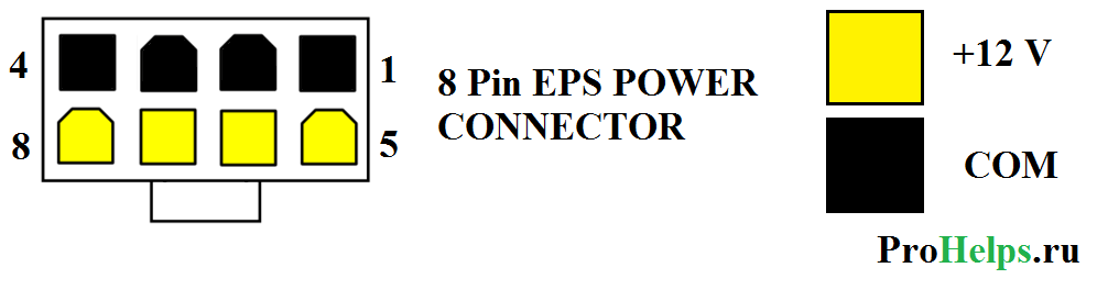
This cable was originally designed for workstations to provide 12 volts of multiple power. But as time has passed a lot of processors require more power and an 8-pin cable is often used instead of a 4-pin 12 volt cable. It is often referred to as "EPS12B" cable.
4+4 Pin EPS +12 Volt Power Connector

 Motherboards can be with 4-pin connector or 8-pin 12 volt connector. Many power supplies are equipped with a 4+4 pin 12 volt cable that is compatible with both 4 and 8 pin continents. A 4+4 power cable has two separate pins 4 pieces. If you connect them together, a 4+4 power cable, then you will have an 8-pin power cable that can be plugged into an 8-pin connector. If you leave the two pieces separate, then you can connect one of the plugs to the motherboard's 4-pin connector.
6-pin PCI Express (PCIe) power cable Connector

This cable is used to provide additional 12 volts of power to the PCI Express expansion card. This connector can provide up to 75W of PCI Express power.
8-pin PCI Express (PCIe) power cable connector

The PCI Express specification version 2.0 released in January 2007 added an 8 pin PCI Express power cable. This is just an 8-pin version of the 6-pin PCI Express with a power cable. Both are mainly used to provide additional power to the graphics card. The older 6-pin version officially delivers no more than 75 watts (although unofficially this can usually deliver significantly more), while the newer 8-pin variant delivers a maximum of 150 watts.
6+2(8) pin PCI Express (PCIe) power cable connector

Some video cards have 6-pin PCI Express power connectors and others 8-pin PCI Express connectors. Many power supplies come with a 6+2 PCI Express power cable that is compatible with both types of graphics cards. In 6+2 PCI Express, the power cable consists of two parts: 6-pin and 2-pin. If you put these two parts together, you will have a full 8-pin PCI-Express connector. But if you split the connector into two parts, then you can only connect a 6-pin.