
This simulator works best on the Chrome browser
Let's take a closer look at Arduino.
Arduino is not a large computer that can be connected to external circuits. Arduino Uno uses Atmega 328P
This is the largest chip on the board. This chip executes programs that are stored in its memory. You can download the program via usb using Arduino IDE. The USB port also provides power to the arduino.
There is a separate power connector. The board has two pins labeled 5v and 3.3v, which are needed to power various devices. You will also find pins marked GND, these are the ground pins (ground is 0V). The Arduino platform also has 14 digital pins, labeled 0 to 13, which connect to external nodes and have two states, high or low (on or off). These contacts can work as outputs or as inputs, i.e. they can either transmit some data and control external devices, or receive data from devices. The next pins on the board are labeled A0-A5. These are analog inputs that can receive data from various sensors. This is especially convenient when you need to measure a certain range, such as temperature. The analog inputs have additional functions that can be enabled separately.

How to use a development board.
The breadboard is needed to temporarily connect the parts, check how the device works, before you solder everything together.
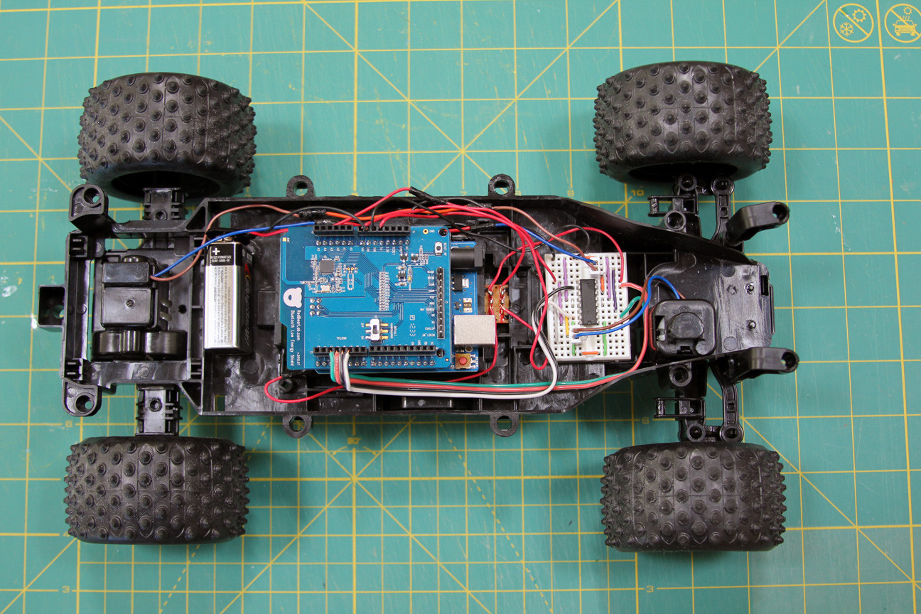
All of the following examples are assembled on a breadboard so that you can quickly make changes to the circuit and reuse parts without bothering with soldering.
The breadboard has rows of holes into which you can insert parts and wires. Some of these holes are electrically connected to each other.
The two top and bottom rows are connected in rows along the entire board. These rows are used to supply power to the circuit. It could be 5V or 3.3V, but either way, the first thing you need to do is connect 5V and GND to the breadboard as shown in the picture. Sometimes these row connections may be broken in the middle of the board, then if you need to, you can connect them as shown in the picture.


The remaining holes, located in the middle of the board, are grouped into groups of five holes. They are used to connect circuit parts.

The first thing we will connect to our microcontroller is an LED. The electrical connection diagram is shown in the picture.

Why is a resistor needed in a circuit? In this case, it limits the current that passes through the LED. Each LED is designed for a certain current, and if this current is higher, the LED will fail. You can find out what value the resistor should be using Ohm's law. For those who don’t know or have forgotten, Ohm’s law says that there is a linear relationship between current and voltage. That is, the more voltage we apply to the resistor, the more current will flow through it.
V=I*R
Where V- voltage across the resistor
I- current through the resistor
R- resistance that needs to be found.
First, we must find out the voltage across the resistor. Most 3mm or 5mm LEDs you will use have an operating voltage of 3V. This means that we need to extinguish 5-3 = 2V at the resistor.
We will then calculate the current passing through the resistor.
Most 3mm and 5mm LEDs glow at full brightness at 20mA. A current greater than this can disable them, while a current of lesser intensity will reduce their brightness without causing any harm.
So, we want to connect the LED to the 5V circuit so that it carries a current of 20mA. Since all the parts are included in one circuit, the resistor will also have a current of 20mA.
We get
2V = 20 mA * R
2V = 0.02A * R
R = 100 Ohm
100 Ohms is the minimum resistance, it is better to use a little more, because LEDs have some variation in characteristics.
IN in this example a 220 ohm resistor is used. Only because the author has a lot of them: wink: .
Insert the LED into the holes in the middle of the board so that its long lead is connected to one of the resistor leads. Connect the second end of the resistor to 5V, and connect the second lead of the LED to GND. The LED should light up.
Please note that there is a difference in how you connect the LED. Current flows from the longer terminal to the shorter one. In the diagram you can imagine that the current flows in the direction where the triangle is directed. Try turning the LED upside down and you will see that it will not light up.
But how you connect the resistor makes no difference at all. You can turn it over or try connecting it to a different pin of the LED, this will not affect the operation of the circuit. It will still limit the current through the LED.
Anatomy of Arduino Sketch.
Programs for Arduino are called sketch. They consist of two main functions. Function setup and function loop
Inside this function you will set all the basic settings. Which pins will work as input or output, which libraries to connect, initialize variables. Function Setup() runs only once during the sketch, when program execution starts.
this is the main function that is executed after setup(). In fact, it is the program itself. This function will run indefinitely until you turn off the power.
Arduino flashing LED

In this example, we will connect an LED circuit to one of the Arduino's digital pins and turn it on and off using a program, and you will also learn several useful functions.


This function is used in setup() part of the program and serves to initialize the pins that you will use as input (INPUT) or exit (OUTPUT). You will not be able to read or write data from the pin until you set it to respectively pinMode. This function has two arguments: pinNumber is the pin number you will use.
Mode-sets how the pin will work. At the entrance (INPUT) or exit (OUTPUT). To light the LED we must give a signal FROM Arduino. To do this, we configure the output pin.
- this function is used to set the state (state) pina (pinNumber). There are two main states (actually 3 of them), one is HIGH, there will be 5V on the pin, that’s something else Low and the pin will be 0v. This means that in order to light the LED we need to set the pin connected to the LED to a high level HIGH.
Delay. Serves to delay the operation of the program for a period specified in msec.
Below is the code that makes the LED blink.
//LED Blink int ledPin = 7;//Arduino pin to which the LED is connected void setup() ( pinMode(ledPin, OUTPUT);// setting the pin as OUTPUT) void loop() ( digitalWrite(ledPin, HIGH);// turn on the LED delay(1000);// delay 1000 ms (1 sec) digitalWrite(ledPin, LOW);//Turn off the LED delay(1000);//wait 1 sec)
Small explanations on the code.
Lines that start with "//" are comments and are ignored by Arduino.
All commands end with a semicolon; if you forget them, you will receive an error message.
ledPin is a variable. Variables are used in programs to store values. In this example, the variable ledPin the value is assigned to 7, this is the Arduino pin number. When the Arduino program encounters a line with a variable ledPin, it will use the value we specified earlier.
So record pinMode(ledPin, OUTPUT) similar to recording pinMode(7, OUTPUT).
But in the first case, you just need to change the variable and it will change in each line where it is used, and in the second case, in order to change the variable, you will have to make changes manually in each command.
The first line indicates the type of the variable. When programming Arduino, it is important to always declare the type of variables. For now it is enough for you to know that INT announces negative and positive numbers.
Below is a simulation of the sketch. Click start to see the circuit in action.
As expected, the LED goes out and comes back on after one second. Try changing the delay to see how it works.
Control of multiple LEDs.
In this example, you will learn how to control multiple LEDs. To do this, install 3 more LEDs on the board and connect them to resistors and Arduino pins as shown below.
In order to turn the LEDs on and off one by one, you need to write a program similar to this:
//Multi LED Blink int led1Pin = 4; int led2Pin = 5; int led3Pin = 6; int led4Pin = 7; void setup() ( //set pins as OUTPUT pinMode(led1Pin, OUTPUT); pinMode(led2Pin, OUTPUT); pinMode(led3Pin, OUTPUT); pinMode(led4Pin, OUTPUT); ) void loop() ( digitalWrite(led1Pin, HIGH );//turn on the LED delay(1000);//delay 1 sec digitalWrite(led1Pin, LOW);//turn off the LED delay(1000);//delay 1 sec //do the same for the other 3 LEDs digitalWrite(led2Pin , HIGH);//light the LED delay(1000);//delay 1 sec digitalWrite(led2Pin, LOW);//extinguish the LED delay(1000);//delay 1 sec digitalWrite(led3Pin, HIGH);//light the LED delay(1000);// delay 1 sec digitalWrite(led3Pin, LOW);//extinguish the LED delay(1000);//delay 1 sec digitalWrite(led4Pin, HIGH);//turn on the LED delay(1000);// delay 1 sec digitalWrite(led4Pin, LOW);//extinguish the LED delay(1000);//delay 1 sec)
This program will work great, but it is not the most rational solution. The code needs to be changed. In order for the program to work over and over again, we will use a construction called .
Loops are useful when you need to repeat the same action several times. In the code above we repeat the lines
DigitalWrite(led4Pin, HIGH); delay(1000); digitalWrite(led4Pin, LOW); delay(1000);
full sketch code in attachment (downloads: 1412)
LED brightness adjustment
Sometimes you will need to change the brightness of the LEDs in the program. This can be done using the command analogWrite()
. This command turns the LED on and off so quickly that the eye cannot see the flickering. If the LED is turned on half the time and off half the time, it will visually appear that it is glowing at half its brightness. This is called pulse width modulation (PWM or PWM in English). Shim is used quite often, since it can be used to control an “analog” component using a digital code. Not all Arduino pins are suitable for these purposes. Only those conclusions near which such a designation is drawn " ~
". You will see it next to pins 3,5,6,9,10,11.
Connect one of your LEDs to one of the PWM pins (for the author this is pin 9). Now run the LED flashing sketch, but first change the command digitalWrite() on analogWrite(). analogWrite() has two arguments: the first is the pin number, and the second is the PWM value (0-255), in relation to LEDs this will be their brightness, and for electric motors the rotation speed. Below is an example code for different LED brightnesses.
//Change the brightness of the LED int ledPin = 9;//an LED is connected to this pin void setup() ( pinMode(ledPin, OUTPUT);// initializing the pin to the output ) void loop() ( analogWrite(ledPin, 255);// full brightness (255/255 = 1) delay(1000);//pause 1 sec digitalWrite(ledPin, LOW);//turn off LED delay(1000);//pause 1 sec analogWrite(ledPin, 191);//brightness by 3/4 (191/255 ~= 0.75) delay(1000);//pause 1 sec digitalWrite(ledPin, LOW);//turn off the LED delay(1000);//pause 1 sec analogWrite(ledPin, 127); //half brightness (127/255 ~= 0.5) delay(1000);//pause 1 sec digitalWrite(ledPin, LOW);//turn off LED delay(1000);//pause 1 sec analogWrite(ledPin, 63); //quarter brightness (63/255 ~= 0.25) delay(1000);//pause 1 sec digitalWrite(ledPin, LOW);//turn off the LED delay(1000);//pause 1 sec)
Try changing the PWM value in the command analogWrite() to see how this affects brightness.
Next, you will learn how to adjust the brightness smoothly from full to zero. You can, of course, copy a piece of code 255 times
analogWrite(ledPin, brightness); delay(5);//short delay brightness = brightness + 1;
But, you understand, this will not be practical. The best way to do this is to use the FOR loop we used earlier.
The following example uses two loops, one to decrease the brightness from 255 to 0
for (int brightness=0;brightness=0;brightness--)( analogWrite(ledPin,brightness); delay(5); )
delay(5) used to slow down the brightness fade-in speed 5*256=1280ms=1.28s)
The first line uses " brightness-" to make the brightness value decrease by 1 each time the loop is repeated. Note that the loop will run until brightness >=0.Replacing the sign >
on the sign >=
we included 0 in the brightness range. This sketch is modeled below. //smoothly change the brightness int ledPin = 9;//an LED is connected to this pin void setup() ( pinMode(ledPin, OUTPUT);// initialization of the output pin) void loop() ( //smoothly increase the brightness (0 to 255 ) for (int brightness=0;brightness=0;brightness--)( analogWrite(ledPin,brightness); delay(5); ) delay(1000);//wait 1 sec //smoothly reduce brightness (255 to 0) for (int brightness=255;brightness>=0;brightness--)( analogWrite(ledPin,brightness); delay(5); ) delay(1000);//wait 1 sec ) )
It's not very visible, but the idea is clear.
RGB LED and Arduino
An RGB LED is actually three different colored LEDs in one package.

By including different LEDs with different brightnesses, you can combine them to create different colors. For Arduino, where the number of brightness levels is 256, you will get 256^3=16581375 possible colors. In reality, of course, there will be fewer of them.
The LED we will use is the common cathode. Those. all three LEDs are structurally connected by cathodes to one terminal. We will connect this pin to the GND pin. The remaining pins, through limiting resistors, must be connected to the PWM pins. The author used pins 9-11. This way it will be possible to control each LED separately. The first sketch shows how to turn on each LED individually.


//RGB LED - test //pin connections int red = 9; int green = 10; int blue = 11; void setup())( pinMode(red, OUTPUT); pinMode(blue, OUTPUT); pinMode(green, OUTPUT); ) void loop())( //turn on/off the red LED digitalWrite(red, HIGH); delay(500) ; digitalWrite(red, LOW); delay(500); //turn on/off the green LED digitalWrite(green, HIGH); delay(500); digitalWrite(green, LOW); delay(500); // turn on/off the blue LED digitalWrite(blue, HIGH); delay(500); digitalWrite(blue, LOW); delay(500); )
The following example uses the commands analogWrite() and to get different random brightness values for the LEDs. You will see different colors changing randomly.
//RGB LED - random colors //pin connections int red = 9; int green = 10; int blue = 11; void setup())( pinMode(red, OUTPUT); pinMode(blue, OUTPUT); pinMode(green, OUTPUT); ) void loop())( //pick a random color analogWrite(red, random(256)); analogWrite( blue, random(256)); analogWrite(green, random(256)); delay(1000);//wait one second )
Random(256)-returns a random number in the range from 0 to 255.
In the attached file is a sketch that will demonstrate smooth color transitions from red to green, then to blue, red, green, etc. (downloads: 388)
The example sketch works, but there is a lot of duplicate code. You can simplify the code by writing your own helper function that will smoothly change from one color to another.
Here's what it will look like: (downloads: 421)
Let's look at the function definition piece by piece. The function is called fader and has two arguments. Each argument is separated by a comma and has a type declared on the first line of the function definition: void fader(int color1, int color2). You see that both arguments are declared as int, and they are given names color1 And color2 as condition variables to define a function. Void means that the function does not return any values, it simply executes commands. If you had to write a function that returned the result of multiplication, it would look like this:
int multiplier(int number1, int number2)( int product = number1*number2; return product; )
Notice how we declared Type int as a return type instead
void.
Inside the function there are commands that you have already used in the previous sketch, only the pin numbers have been replaced with color1 And color2. The function is called fader, its arguments are calculated as color1 = red And color2 = green. The archive contains a complete sketch using functions (downloads: 321)
Button
The next sketch will use a button with normally open contacts, without latching.

This means that while the button is not pressed, no current flows through it, and after being released, the button returns to its original position.
In addition to the button, the circuit uses a resistor. In this case, it does not limit the current, but “pulls” the button to 0V (GND). Those. Until the button is pressed, the Arduino pin it is connected to will go low. The resistor used in the circuit is 10 kOhm.

//determine when the button is pressed int buttonPin = 7; void setup())( pinMode(buttonPin, INPUT);//initialize the pin to the input Serial.begin(9600);//initialize the serial port) void loop())( if (digitalRead(buttonPin)==HIGH)(//if button pressed Serial.println("pressed"); // display "pressed" ) else ( Serial.println("unpressed"); // otherwise "unpressed" ) )
There are several new commands in this sketch.
-This command takes the value of High (high level) and low (low level), the output that we are checking. This output must first be configured as an input in setup().
; //where buttonPin is the pin number where the button is connected.
The serial port allows the Arduino to send messages to the computer while the controller itself is executing the program. This is useful for debugging a program, sending messages to other devices or applications. To enable data transfer via a serial port (also called UART or USART), you need to initialize it in setup()
Serial.begin() has only one argument - this is the data transfer speed between the Arduino and the computer.
The sketch uses a command to display a message on the screen in the Arduino IDE (Tools >> Serial Monitor).
- the design allows you to control the progress of program execution by combining several checks in one place.
If digitalRead returns HIGH, then the word "pressed" is displayed on the monitor. Else (otherwise) the word “released” is displayed on the monitor. Now you can try turning the LED on and off by pressing a button.
//button press detection with LED output int buttonPin = 7; int ledPin = 8; void setup())( pinMode(buttonPin, INPUT);//this time we will set button pin as INPUT pinMode(ledPin, OUTPUT); Serial.begin(9600); ) void loop())( if (digitalRead(buttonPin)= =HIGH)( digitalWrite(ledPin,HIGH); Serial.println("pressed"); ) else ( digitalWrite(ledPin,LOW); Serial.println("unpressed"); ) )
Analog input.
analogRead allows you to read data from one of the Arduino analog pins and displays a value in the range from 0 (0V) to 1023 (5V). If the voltage at the analog input is 2.5V, then 2.5 / 5 * 1023 = 512 will be printed
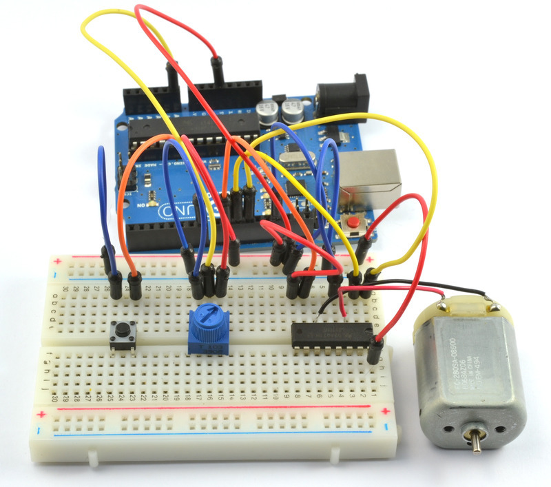
analogRead has only one argument - This is the analog input number (A0-A5). The following sketch shows the code for reading the voltage from the potentiometer. To do this, connect a variable resistor, the outer terminals to the 5V and GND pins, and the middle terminal to the A0 input.

Run the following code and see in the serial monitor how the values change depending on the rotation of the resistor knob.
//analog input int potPin = A0;//the central pin of the potentiometer is connected to this pin void setup())( //analog pin is included as an input by default, so initialization is not needed Serial.begin(9600); ) void loop())( int potVal = analogRead(potPin);//potVal is a number between 0 and 1023 Serial.println(potVal); )
The following sketch combines the button click sketch and the LED brightness control sketch. The LED will turn on from the button, and the brightness will be controlled by a potentiometer.
//button press detection with LED output and variable intensity int buttonPin = 7; int ledPin = 9; int potPin = A0; void setup())( pinMode(buttonPin, INPUT); pinMode(ledPin, OUTPUT); Serial.begin(9600); ) void loop())( if (digitalRead(buttonPin)==HIGH)(//if button pressed int analogVal = analogRead(potPin); int scaledVal = map(analogVal, 0, 1023, 0, 255); analogWrite(ledPin, scaledVal);//turn on led with intensity set by pot Serial.println("pressed"); ) else ( digitalWrite(ledPin, LOW);//turn off if button is not pressed Serial.println("unpressed"); ) )
Introduction
Freeduino/Arduino is programmed in a special programming language - it is based on C/C++, and allows you to use any of its functions. Strictly speaking, there is no separate Arduino language, just as there is no Arduino compiler - written programs are converted (with minimal changes) into a program in C/C++, and then compiled by the AVR-GCC compiler. So, in fact, a variant of C/C++ specialized for AVR microcontrollers is used.
The difference is that you get a simple development environment and a set of basic libraries that simplify access to the peripherals located “on board” the microcontroller.
Agree, it is very convenient to start working with a serial port at a speed of 9600 bits per second, making a call in one line:
Serial.begin(9600);
And when using “naked” C/C++, you would have to deal with the documentation for the microcontroller and call something like this:
UBRR0H = ((F_CPU / 16 + 9600 / 2) / 9600 - 1) >> 8;
UBRR0L = ((F_CPU / 16 + 9600 / 2) / 9600 - 1);
sbi(UCSR0B, RXEN0);
sbi(UCSR0B, TXEN0);
sbi(UCSR0B, RXCIE0);
Here is a brief overview of the main functions and features of Arduino programming. If you are not familiar with the syntax of the C/C++ languages, we recommend that you refer to any literature on this issue or Internet sources.
On the other hand, all the examples presented are very simple, and most likely you will not have any difficulties understanding the source texts and writing your own programs even without reading additional literature.
More complete documentation (in English) is presented on the official website of the project - http://www.arduino.cc. There is also a forum, links to additional libraries and their descriptions.
By analogy with the description on the official website of the Arduino project, a “port” refers to a microcontroller contact connected to a connector under the corresponding number. In addition, there is a serial communication port (COM port).
Program structure
In your program you must declare two main functions: setup() and loop().
The setup() function is called once, after every power-up or reset of the Freeduino board. Use it to initialize variables, set operating modes of digital ports, etc.
The loop() function sequentially executes the commands described in its body over and over again. Those. After the function completes, it will be called again.
Let's look at a simple example:
void setup() // initial settings
{
beginSerial(9600); // setting the serial port speed to 9600 bps
pinMode(3, INPUT); // setting the 3rd port for data input
}
// The program checks the 3rd port for the presence of a signal on it and sends a response to
// as a text message to the computer's serial port
void loop() // program body
{
if (digitalRead(3) == HIGH) // condition for polling the 3rd port
serialWrite("H"); // send a message in the form of the letter "H" to the COM port
else
serialWrite("L"); // send a message in the form of the letter "L" to the COM port
delay(1000); // delay 1 sec.
}
pinMode(port, mode);
Description:
Configures the specified port to input or output a signal.
Options:
port – the number of the port whose mode you want to set (an integer value from 0 to 13).
mode - either INPUT (input) or OUTPUT (output).
pinMode(13, OUTPUT); //13th pin will be the output
pinMode(12, INPUT); //and the 12th is the input
Note:
Analog inputs can be used as digital inputs/outputs by accessing them using numbers 14 (analog input 0) to 19 (analog input 5)
digitalWrite(port, value);
Description:
Sets the voltage level to high (HIGH) or low (LOW) on the specified port.
Options:
port: port number
value: HIGH or LOW
digitalWrite(13, HIGH); // set pin 13 to “high” state
value = digitalRead(port);
Description:
Reads the value on the specified port
Options:
port: polled port number
Return value: returns the current value on the port (HIGH or LOW) of type int
int val;
val = digitalRead(12); // poll the 12th pin
Note:
If there is nothing connected to the port being read, then the digitalRead() function may return HIGH or LOW values erratically.
Analog signal input/output
value = analogRead(port);
Description:
Reads a value from the specified analog port. Freeduino contains 6 channels, analog-to-digital converter of 10 bits each. This means that the input voltage from 0 to 5V is converted to an integer value from 0 to 1023. The readout resolution is: 5V/1024 values = 0.004883 V/value (4.883 mV). It takes approximately 100 nS (0.0001 C) to read an analog input value, so the maximum read rate is approximately 10,000 times per second.
Options:
Return Value: Returns an int number in the range 0 to 1023 read from the specified port.
int val;
val = analogRead(0); // read the value at the 0th analog input
Note:
Analog ports are defined as signal input by default and, unlike digital ports, do not need to be configured by calling the pinMode function.
analogWrite(port, value);
Description:
Outputs an analog value to the port. This function works on: 3, 5, 6, 9, 10, and 11 Freeduino digital ports.
Can be used to change the brightness of an LED, control a motor, etc. After calling the analogWrite function, the corresponding port begins to operate in voltage pulse-width modulation mode until there is another call to the analogWrite function (or digitalRead / digitalWrite functions on the same port).
Options:
port: number of the analog input being polled
value: an integer between 0 and 255. A value of 0 generates 0 V on the specified port; a value of 255 generates +5V on the specified port. For values between 0 and 255, the port begins to rapidly alternate between 0 and +5 V voltage levels - the higher the value, the more often the port generates the HIGH (5 V) level.
analogWrite(9, 128); // set pin 9 to a value equivalent to 2.5V
Note:
There is no need to call pinMode to set the port to output signals before calling analogWrite.
The signal generation frequency is approximately 490 Hz.
time = millis();
Description:
Returns the number of milliseconds since the Freeduino executed the current program. The counter will overflow and reset after approximately 9 hours.
Return value: returns an unsigned long value
unsigned long time; // declaration of a time variable of type unsigned long
time = millis(); // transfer the number of milliseconds
delay(time_ms);
Description:
Pauses the program for the specified number of milliseconds.
Options:
time_ms – program delay time in milliseconds
delay(1000); //pause 1 second
delayMicroseconds
delayMicroseconds(time_μs);
Description:
Pauses the program for the specified number of microseconds.
Options:
time_μs – program delay time in microseconds
delayMicroseconds(500); //pause 500 microseconds
pulseIn(port, value);
Description:
Reads a pulse (high or low) from a digital port and returns the pulse duration in microseconds.
For example, if the "value" parameter is set to HIGH when calling the function, then pulseIn() waits for a high signal level to arrive on the port. From the moment it arrives, the countdown begins until a low signal level is received at the port. The function returns the pulse length (high level) in microseconds. Works with pulses from 10 microseconds to 3 minutes. Note that this function will not return a result until a pulse is detected.
Options:
port: port number from which we read the pulse
value: pulse type HIGH or LOW
Return value: returns the pulse duration in microseconds (type int)
int duration; // declaration of a duration variable of type int
duration = pulseIn(pin, HIGH); // measure the pulse duration
Serial data transmission
Freeduino has a built-in controller for serial data transmission, which can be used both for communication between Freeduino/Arduino devices and for communication with a computer. On a computer, the corresponding connection is represented by a USB COM port.
Communication occurs over digital ports 0 and 1, and therefore you will not be able to use them for digital I/O if you are using serial functions.
Serial.begin(baud_rate);
Description:
Sets the COM port information transfer rate in bits per second for serial data transmission. In order to communicate with a computer, use one of these standardized speeds: 300, 1200, 2400, 4800, 9600, 14400, 19200, 28800, 38400, 57600, or 115200. You can also define other speeds when communicating with another microcontroller by ports 0 and 1.
Options:
baud_rate: Data flow rate in bits per second.
Serial.begin(9600); //set the speed to 9600 bps
Serial.available
count = Serial.available();
Description:
Bytes received via the serial port end up in the microcontroller buffer, from where your program can read them. The function returns the number of bytes accumulated in the buffer. The serial buffer can store up to 128 bytes.
Return value:
Returns an int value - the number of bytes available for reading in the serial buffer, or 0 if nothing is available.
if (Serial.available() > 0) ( // If there is data in the buffer
// there should be data reception and processing here
}
char = Serial.read();
Description:
Reads the next byte from the serial port buffer.
Return value:
The first available byte of incoming data from the serial port, or -1 if there is no incoming data.
incomingByte = Serial.read(); // read byte
Description:
Clears the serial port input buffer. Data in the buffer is lost, and further calls to Serial.read() or Serial.available() will make sense for data received after the Serial.flush() call.
Serial.flush(); // Clear the buffer - start receiving data “from scratch”
Description:
Output data to serial port.
Options:
The function has several call forms depending on the type and format of the output data.
Serial.print(b, DEC) prints an ASCII string - the decimal representation of the number b.
int b = 79;
Serial.print(b, HEX) prints an ASCII string - the hexadecimal representation of the number b.
int b = 79;
Serial.print(b, OCT) prints an ASCII string - the octal representation of the number b.
int b = 79;
Serial.print(b, OCT); //will output the string “117” to the port
Serial.print(b, BIN) prints an ASCII string - the binary representation of the number b.
int b = 79;
Serial.print(b, BIN); //will output the string “1001111” to the port
Serial.print(b, BYTE) prints the low byte of b.
int b = 79;
Serial.print(b, BYTE); //will display the number 79 (one byte). In the monitor
//from the serial port we get the symbol “O” - its
//code is 79
Serial.print(str) if str is a string or character array, transfers str to the COM port byte byte.
char bytes = (79, 80, 81); //array of 3 bytes with values 79,80,81
Serial.print("Here our bytes:"); //outputs the line “Here our bytes:”
Serial.print(bytes); //outputs 3 characters with codes 79,80,81 –
//these are the characters "OPQ"
Serial.print(b) if b is of type byte or char, prints the number b itself to the port.
char b = 79;
Serial.print(b); //will output the character “O” to the port
Serial.print(b) if b is of type integer, prints the decimal representation of b to the port.
int b = 79;
Serial.print(b); //will output the string “79” to the port
Description:
The Serial.println function is similar to the Serial.print function, and has the same call options. The only difference is that two additional characters are output after the data - a carriage return character (ASCII 13, or "\r") and a new line character (ASCII 10, or "\n").
Example 1 and example 2 will output the same thing to the port:
int b = 79;
Serial.print(b, DEC); //will output the string “79” to the port
Serial.print("\r\n"); //will display the characters "\r\n" – line feed
Serial.print(b, HEX); //will output the string “4F” to the port
Serial.print("\r\n");//will print the characters "\r\n" – line feed
int b = 79;
Serial.println(b, DEC); //will output the string “79\r\n” to the port
Serial.println(b, HEX); //will output the string “4F\r\n” to the port
In the serial port monitor we get.
Historically, the Arduino software part consisted of an integrated software environment (IDE) that allowed you to write, compile, and upload the written code to the hardware. The ArduinoIDE environment and the Wiring language itself are based primarily on Processing, and indirectly on C/C++. In fact, the Arduino IDE is a big hodgepodge, not for fun, but for convenience.
Even externally andArduinoIDE andProcessing are similar
What does the program (sketch) consist of?
Each program, no matter how complex it may seem, consists of separate sets blocks code, which is denoted by curly braces (). A minimal program requires only 2 blocks: setup and loop. Their presence is mandatory in any C++ program for Arduino, otherwise you may get an error at the compilation stage.
void setup() ( ) void loop() ( )
In the setup() function, the initial settings of variables and registers occur. After setup() completes, control passes to the loop() function, which is an infinite loop written in the body (between ( ) ). It is these commands that perform all the algorithmic actions of the controller.
Hardware "Hello,
world! - blinking LED.
What begins the first acquaintance with Arduino at the interface of software and hardware is the blinking LED.

First you need to supplement the minimum program. For Arduino (for example UNO), we connect an LED to pin 12 and GND (the color of the LED itself is chosen from personal preference).
Void setup() ( pinMode(12, OUTPUT); ) void loop() ( digitalWrite(12, HIGH); delay(100); digitalWrite(12, LOW); delay(900); )
Do Ctrl+C -> Ctrl+V, compile, load, control. We see a light show that lasts no more than a second. Let's figure out why this happens.
We added several to previously empty blocks expressions
. They were placed between the curly braces of the setup and loop functions.
Each expression is an instruction for the processor. Expressions within one block are executed one after another, strictly in order, without any pauses or switching. That is, if we are talking about one specific block of code, it can be read from top to bottom to understand what is being done.
What happens between{ }
?
As you know, Arduino pins can work as both output and input. When we want to control something, we need to transfer the control pin to the output state. This is done by expression in the function setup:
pinMode(12, OUTPUT); In this situation, the expression carries out function call
. In pinMode, the pin specified by number is set to the specified mode (INPUT or OUTPUT). Which pin and which mode we are talking about is indicated in parentheses, separated by commas. In our case, we want the 12th pin to act as an output. OUTPUT means output, INPUT means input. Qualifying values such as 12 and OUTPUT are called function arguments
. How many arguments a function has depends on the nature of the function and the will of its creator. Functions can have no arguments at all, as is the case with setup and loop.
Next, move on to the loop block, in order:
-call the built-in function digitalWrite. It is designed to apply a logical zero (LOW, 0 volt) or a logical one (HIGH, 5 volt) to a given pin. Two arguments are passed to the digitalWrite function: the pin number and the logical value.
- call the delay function. This, again, is a built-in function that causes the processor to “sleep” for a certain time. It takes just one argument: the time in milliseconds to sleep. In our case it is 100 ms. As soon as the 100 ms expires, the processor wakes up and immediately moves on to the next expression.
- call the built-in function digitalWrite. Only this time the second argument is LOW. That is, we set a logical zero on the 12th pin -> apply 0 volts -> turn off the LED.
- calling the delay function. This time we “sleep” a little longer – 900 ms.
As soon as the last function is executed, the loop block ends and everything happens all over again. In fact, the conditions presented in the example are quite variable, and you can play with the delay values, connect several LEDs and make something like a traffic light or a police flasher (it all depends on the imagination and will of the creator).
Instead of a conclusion, a little about cleanliness.
In fact, all spaces, line breaks, tab characters don't mean much to the compiler. Where there is a space, there can be a line break and vice versa. In fact, 10 spaces in a row, 2 line breaks and 5 more spaces are the equivalent of one space.
With the help of empty space, you can make a program understandable and visual, or, on the contrary, disfigure it beyond recognition. For example, the example program can be changed like this:
void setup() ( pinMode(12, OUTPUT); ) void loop () ( digitalWrite(12,HIGH); delay(100); digitalWrite(12,LOW); delay(900); )
To prevent anyone from bleeding from their eyes while reading, you can follow a few simple rules:
1. Always, at the start of a new block between( And ) increase the indentation. Typically 2 or 4 spaces are used. Choose one of the values and stick to it throughout.
Void loop() ( digitalWrite(12, HIGH); delay(100); digitalWrite(12, LOW); delay(900); )
2.
Just like in regular language: put a space after commas.
digitalWrite(12, HIGH);
3.
Place the start-of-block character (on a new line at the current indentation level or at the end of the previous one. And the end-of-block character) on a separate line at the current indentation level:
void setup() ( pinMode(12, OUTPUT); ) void setup() ( pinMode(12, OUTPUT); )
4.
Use empty lines to separate blocks of meaning:
void loop() ( digitalWrite(12, HIGH); delay(100); digitalWrite(12, LOW); delay(900); digitalWrite(12, HIGH); delay(100); digitalWrite(12, LOW); delay( 900); )
5.
In order for your child to enjoy reading, there are so-called comments. These are constructs in the program code that are completely ignored by the compiler and only matter to the person reading it. Comments can be multi-line or single-line:
/* this is a multi-line comment */ // this is a single-line comment
This introductory article is for those who have already unpacked a dozen or two colored boxes from construction sets with their child, built hundreds of different structures and filled all available containers in the closet with Lego parts. If you are ready to move to the next level: with electronics, microcontrollers, sensors and smart devices, then it’s time to experiment with Arduino!
In this series of articles we will collect the most important things you need to know about Arduino in order to start teaching children yourself. Even if you have never picked up a soldering iron and the words “controller” and “controller” have approximately the same meaning for you, you can be sure that you will still succeed! The world of electronics and robotics today is full of simple and very convenient solutions that allow you to create very interesting projects practically from scratch. Our tutorial will help you quickly navigate and take your first steps.
In everyday language, Arduino is a device into which you can plug many different devices and make them work together using a program written in the Arduino language in a special programming environment.
Most often the board looks like this:
The figure shows one of the Arduino boards - Arduino Uno. We will study it in more detail in the following lessons.
You can plug wires into the board and connect many different elements. Most often, a breadboard for solderless mounting is used for connection. You can add LEDs, sensors, buttons, motors, communication modules, relays and create hundreds of interesting smart device designs. The Arduino board is a smart socket that will turn everything connected on and off depending on how it was programmed.


All work on the project is divided into the following stages:
- We come up with an idea and design it.
- We collect electrical diagram. Here we need a breadboard, which simplifies the installation of elements. Of course, you will need skills in working with electronic devices and ability.
- We connect to the computer via USB.
- and write it to the board literally by pressing one button on the screen in .
- Disconnect from the computer. Now the device will work autonomously - when the power is turned on, it will be controlled by the program that we wrote into it.
The program and programming environment look like this:

The screen shows a program (in Arduino slang the text of the program is called “sketch”), which will blink with a light connected to input 13 on the Arduino UNO board. As you can see, the program is quite simple and consists of instructions that are understandable for those who know English. The Arduino programming language uses its own dialect of the C++ language, but all C++ features are supported.
There is another option for writing code - a visual editor. There is no need to write anything here - you can simply move the blocks and put together the desired algorithm from them. The program will be loaded into the connected board with one click of the mouse button!

Overall, everything looks pretty clear, doesn't it? It remains to figure out the details.
Quick start with Arduino
First, let's understand what and what we are going to do. What is Arduino and how to use it? If you are already familiar with the topic, feel free to skip ahead. If not, let's do a short dive together.
Arduino is...
Arduino is not a brand or the name of a kit supplier. This is a general name for a whole family of different technologies and an open platform, which includes both hardware devices (controller boards and compatible equipment) and software designed to control hardware. At its core, Arduino is an infrastructure and environment in which we can assemble electronic and mechanical components compatible with each other into a single device, and then through a regular computer, in two minutes, program the behavior of these same pieces of hardware the way we need.
Arduino is a bridge from the virtual computer world to the world of real things and devices. Having written a program on a regular computer, we use it to control not virtual objects, but rather real sensors, motors, and screens. We change the world around us - simply by programming on a computer, using free software and many ready-made examples of libraries.
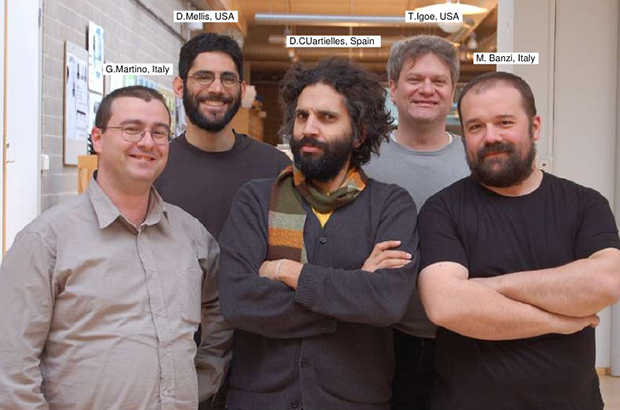
The technology received its name, as often happens, quite by accident. The source of inspiration was a bar where the future creators of Arduino liked to drink a cup of tea. The name of the establishment was exactly that - Arduino, after the main historical figure of the city of Ivrea, King Arduino. The king did not leave any bright mark in history and was considered a failure, but thanks to the team of developers of the new platform, he gained new popularity and is now known to millions of people around the globe.
Why Arduino?
The beauty of Arduino lies in the following simple advantages:
- Simplicity. Yes, yes - exactly simplicity (although Lego and other toys are undoubtedly more familiar, but we are not comparing with them). For young electronics developers, Arduino “hides” a huge number of different technical issues. Many quite complex projects can be created very quickly, without a long immersion in details. And this is very important for a child - not to lose interest until the first result obtained with his own hands.
- Popularity. Arduino is extremely popular, you can easily find answers to any questions on numerous forums or websites. The Arduino community is vast and friendly - there are relatively few life-hardened, snobby engineers there and full of hobbyists and beginners who are happy to share their joy from what they have found and learned. This, of course, leaves an imprint on the quality of advice, but as a rule, even the most complex issues can be quickly resolved with the help of forums and websites.
- Availability. Both the technology itself and almost all software are released under open licenses and you can freely use other people’s developments and schemes, and in many cases even for commercial use. This saves a lot of time and allows you to take big steps, building on the experience of previous researchers.
- Cheapness. A kit for your first lessons in electronics and programming can be purchased for less than 500 rubles. Full-fledged robotics courses are possible with. No other technology will allow you to enter the world of real educational robotics so quickly and so effectively.
Where to begin?
If you want to do robotics using Arduino, then you will need this gentleman's kit:
- with USB cable for connecting to a computer.
- and wires.
- A set of basic electronic components and an adapter for a crown battery.
- Environment installed on the computer
In the future, if the classes really captivate you and there is a desire to continue experiments, then the list of equipment will expand:
- Screens and indicators.
- Motors and , relays and .
- Communication modules.
- Various additional modules and shields
If the first steps give results, over time you will recognize half of the people standing in line at the post office (if you don’t already know them), and the postmen will recognize you by sight when they meet you and nervously run across to the other side of the road.
How to buy Arduino?
Before you learn something useful, you must first buy something useful. To experiment with electronics, you will need the same electronics in the form of a construction set or separate boards. It is recommended to buy a not very expensive domestic kit with the main components and then order sensors, motors, controllers and other treasures from Aliexpress.
Here are some of the most interesting and attractively priced options for purchasing boards and kits for your first lessons:
 A small and very cheap starter kit that contains everything you need for your first projects A small and very cheap starter kit that contains everything you need for your first projects
|
 Very high quality starter kit from the famous manufacturer Keyestudio Very high quality starter kit from the famous manufacturer Keyestudio
|
 Classic Arduino starter kit, enough for dozens of different projects Classic Arduino starter kit, enough for dozens of different projects
|
 Advanced starter kit Robotlinking with Arduino UNO and Mega2560. Instructions and convenient box Advanced starter kit Robotlinking with Arduino UNO and Mega2560. Instructions and convenient box
|
 Simple kit with breadboard, LEDs, resistors and wires for connection Simple kit with breadboard, LEDs, resistors and wires for connection
|
 An unusual kit for rapid prototyping with convenient RJ11 connectors - even a small child can handle it! An unusual kit for rapid prototyping with convenient RJ11 connectors - even a small child can handle it!
|
If you still want to buy the Arduino board separately, here are some interesting links:
 High-quality Arduino UNO R3 board based on CH340G. Set without cable with a minimum price of about 220 rubles High-quality Arduino UNO R3 board based on CH340G. Set without cable with a minimum price of about 220 rubles
|
 MegaPower Uno board based on the original ATmega328 R3, FTDI FT232RL MegaPower Uno board based on the original ATmega328 R3, FTDI FT232RL
|
 An excellent option from KeyeStudio – UNO R3 MEGA328P ATMEGA16U2 with combined Sensor Shield An excellent option from KeyeStudio – UNO R3 MEGA328P ATMEGA16U2 with combined Sensor Shield
|
Let's summarize the lesson
In this short initial article, we learned what Arduino is, why this technology is called exactly what it is, what typical projects using Arduino controllers. It's very easy to start creating interesting technical projects - you don't have to be an electronics engineer to do it. Just take an Arduino board, assemble the desired electronic circuit using it (you can find many ready-made examples on the Internet), connect the controller to your computer and download the program. The smart device is ready!
In the following lessons, we will learn how the controller works, disassemble the Arduino Uno board, and launch our first project.
Useful links to tutorials and websites on Arduino
Official Arduino websites:
- “Almost” official website in Russian: http://arduino.ru/
Excellent sites with a lot of useful information
Ardublock is a graphical programming language for Arduino designed for beginners. This environment is quite easy to use, easy to install, and almost completely translated into Russian. A visually designed program that resembles blocks...
Interrupts are a very important mechanism in Arduino that allows external devices to interact with the controller when various events occur. By installing a hardware interrupt handler in the sketch, we can respond to a button being turned on or off, a keyboard press,...
Serial.print() and Serial.println() are the main functions of Arduino to transfer information from the Arduino board to the computer through the serial port. The most popular Arduino Uno, Mega, Nano boards do not have a built-in display, so...
Is it possible to do Arduino projects without the Arduino board itself? It turns out, quite. Thanks to numerous online services and programs that have their own name: emulator or Arduino simulator. The most popular representatives of such programs are...
Serial begin is an extremely important Arduino instruction; it allows the controller to establish a connection with external devices. Most often, this “external device” is the computer to which we connect the Arduino. That's why Serial begin is more intense...
A global variable in Arduino is a variable whose scope extends to the entire program, it is visible in all modules and functions. In this article we will look at several examples of using global variables...
Arduino arrays are a language element actively used by programmers to work with sets of data of the same type. Arrays are found in almost all programming languages, Arduino is no exception, the syntax of which is very similar...